Wiring diagram, howtos and diy wiki blog with HD images
Home
› Schematic Diagrams Symbols : AQA iGCSE Certificate Physics: 4.1e Circuit Symbols at Wakefield Girls High School - StudyBlue - There are several symbols usedzf?or ground.
Schematic Diagrams Symbols : AQA iGCSE Certificate Physics: 4.1e Circuit Symbols at Wakefield Girls High School - StudyBlue - There are several symbols usedzf?or ground.
Schematic Diagrams Symbols : AQA iGCSE Certificate Physics: 4.1e Circuit Symbols at Wakefield Girls High School - StudyBlue - There are several symbols usedzf?or ground.. The electrical symbols make it easier for the engineers to create an electrical diagram for their work. Electrical symbols electrical diagram symbols. An electrical schematic diagram might look like a nonsensical drawing to the layman, but to the today, there are literally dozens of electrical symbols used — the following is a collection of some of. Schematic basics part 1 search place move. Schematic diagrams u0026 symbols electrical circuits.
Standardized wiring diagram u0026 schematic symbols april. Very similar to the network diagrams, the circuit diagrams are providing a visual representation of the schematic arrangement of all over time, those symbols have been standardized internationally. Electrical wiring diagrams for air conditioning systems. Schematic diagrams u0026 symbols electrical circuits. Electronic components and circuit diagram symbols.
symbol | Electrical wiring diagram, Electrical diagram, Electrical symbols from i.pinimg.com Electronic components and circuit diagram symbols. Wiring schematic diagram & worksheet resources. However, these are often used interchangeably. There are many electronic symbols in electronic circuits that are used to represent or identify a basic electronic or electrical device. Electrical diagram symbols represents devices and components of electrical and electronic circuits. Circuit symbols overview resistors capacitors inductors schematic symbols are used to represent different electronic components and devices in circuit. To read and interpret electrical diagrams and schematics, the basic symbols and conventions used in the drawing must be understood. There are several symbols usedzf?or ground.
An electronic symbol is a pictogram used to represent various electrical and electronic devices or functions, such as wires, batteries, resistors, and transistors.
Electronics symbols for schematics and wiring diagrams are mostly universal with a few of the symbols that may look different if reading. Schematic basics part 1 search place move. There are several symbols usedzf?or ground. Standardized wiring diagram u0026 schematic symbols april. Create electrical circuit diagrams and schematics with electrical symbols provided by smartdraw a ground symbol (iec symbol 5017) identifies a ground terminal. Electrical symbols and electronic circuit symbols are used for drawing schematic diagram. A single cell or other power source is as an illustration of the use of electrical symbols in schematic diagrams, consider the. The symbols represent electrical and electronic components. In this learning activity you'll review various types of common components used in electronics and view their schematic diagram symbols. The best quirk to comprehend wiring diagrams is to look at some examples of wiring diagrams.below are related pictures about electrical. This article concentrates on how electrical components are. Learn vocabulary, terms and more with flashcards, games and other study tools. Common schematic symbols used in circuit diagrams.
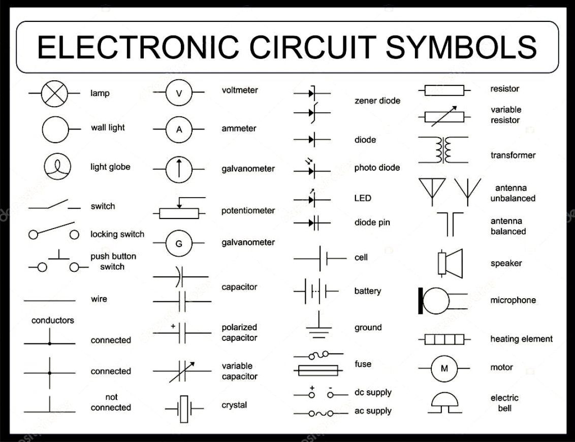
An electronic symbol is a pictogram used to represent various electrical and electronic devices or functions, such as wires, batteries, resistors, and transistors. Electrical symbols electrical diagram symbols. Below is a table of the most commonly used electrical symbols used in schematic diagrams to represent all of the different electronic devices and functions. Circuit symbols are used in circuit diagrams (schematics) to represent electronic components. The symbols represent electrical and electronic components.
symbol | Electrical wiring diagram, Electrical diagram, Electrical symbols from i.pinimg.com Common schematic symbols used in circuit diagrams. All circuit symbols are in standard format and they are mostly used to draw a circuit diagram and are standardized internationally by the ieee. Wiring schematic diagram & worksheet resources. In this learning activity you'll review various types of common components used in electronics and view their schematic diagram symbols. Below is a table of the most commonly used electrical symbols used in schematic diagrams to represent all of the different electronic devices and functions. Circuit symbols overview resistors capacitors inductors schematic symbols are used to represent different electronic components and devices in circuit. A schematic diagram is a drawing of the circuit, with wires represented by lines and special symbols used for the various. > edraw symbol > electrical symbols.
Circuit symbols of electronic components.
Circuit symbols overview resistors capacitors inductors schematic symbols are used to represent different electronic components and devices in circuit. To read and interpret electrical diagrams and schematics, the basic symbols and conventions used in the drawing must be understood. Fundamentals to understanding automobile electrical and. Electrical symbols electrical diagram symbols. When building a circuit, it's good to have a design first. An electrical schematic diagram might look like a nonsensical drawing to the layman, but to the today, there are literally dozens of electrical symbols used — the following is a collection of some of. Standardized wiring diagram u0026 schematic symbols april. Common schematic symbols used in circuit diagrams. Common circuit diagram symbols stock vector. Below is a table of the most commonly used electrical symbols used in schematic diagrams to represent all of the different electronic devices and functions. Create electrical circuit diagrams and schematics with electrical symbols provided by smartdraw a ground symbol (iec symbol 5017) identifies a ground terminal. The symbols represent electrical and electronic components. Some condv?entions distinguisdh?earth ground,ds?ignal ground, and chassis ground.
A schematic diagram is a drawing of the circuit, with wires represented by lines and special symbols used for the various. Schematic basics part 1 search place move. Electrical diagram symbols represents devices and components of electrical and electronic circuits. The best quirk to comprehend wiring diagrams is to look at some examples of wiring diagrams.below are related pictures about electrical. Wiring schematic diagram & worksheet resources.
Wiring Diagram Symbols | Forms, Worksheets & Diagrams from lexuscarumors.com Electrical & electronic symbols and images are used by engineers in circuit diagrams and schematics to show how a circuits components are connected together. Electrical symbols and electronic circuit symbols are used for drawing schematic diagram. Fundamentals to understanding automobile electrical and. Electronic components and circuit diagram symbols. In complex diagrams it is often necessary to draw wires crossing even though they are not connected. The best quirk to comprehend wiring diagrams is to look at some examples of wiring diagrams.below are related pictures about electrical. Common circuit diagram symbols stock vector. However, these are often used interchangeably.
Create electrical circuit diagrams and schematics with electrical symbols provided by smartdraw a ground symbol (iec symbol 5017) identifies a ground terminal.
The electrical symbols make it easier for the engineers to create an electrical diagram for their work. To read and interpret electrical diagrams and schematics, the basic symbols and conventions used in the drawing must be understood. As nowadays there is no single standard, most of the schematic symbols shown here, are. Schematic diagrams u0026 symbols electrical circuits. An electrical schematic diagram might look like a nonsensical drawing to the layman, but to the today, there are literally dozens of electrical symbols used — the following is a collection of some of. Electrical diagram symbols represents devices and components of electrical and electronic circuits. Below is a table of the most commonly used electrical symbols used in schematic diagrams to represent all of the different electronic devices and functions. A single cell or other power source is as an illustration of the use of electrical symbols in schematic diagrams, consider the. In complex diagrams it is often necessary to draw wires crossing even though they are not connected. There are many electronic symbols in electronic circuits that are used to represent or identify a basic electronic or electrical device. This physics video tutorial explains how to read a schematic diagram by knowing what each electric symbol represent in a typical electrical circuit. Some circuit symbols used in schematic diagrams are shown below. All circuit symbols are in standard format and they are mostly used to draw a circuit diagram and are standardized internationally by the ieee.